UPDATE ON BUCKLE ASSEMBLY SERVICE BULLETINS – 1111475 & 1111548
Information for Restraint Systems with Buckle Assembly Series Part Numbers 1111475 and 1111548
Parker Meggitt has been made aware of a 2012 manufacturing quality issue for specific lots of Restraint System Buckle Assembly Part Numbers. Sub-component zinc chromate screws were improperly processed for zinc chromate plating.
The resulting improper plating resulted in some screws having hydrogen embrittlement. In 2013 the zinc chromate screws design was replaced with stainless steel screws design (that does not require zinc chromate plating) and therefore removes the chance for hydrogen embrittlement.
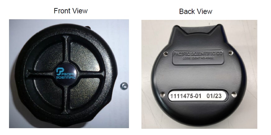
P/N 1111475
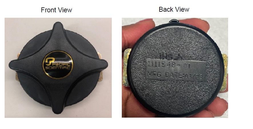
P/N 1111548
To address this quality issue Parker Meggitt have released two Service Bulletins respectively that are available to download below. These Service Bulletins will provide details for the applicability, inspection, replace damaged sub-components, and details needed to address this quality issue.
1111475-25-001-2023_45402_SB_002
1111548-25-001-2023_45402_SB_002
Instructions
Please find below the additional supporting material in regards to the service bulletins mentioned above:
Screw head type inspection PN 1111475 - HEX SCREW
- Hold the rotary buckle with the back plate vertical and with one screw hole at a 12:00 position.
- Place a magnet against the buckle back over the through (bolt) hole at the 12:00 position and let go of the magnet.
- Repeat for other three bolt holes.
- If the magnet slips down to and stops near the center of the buckle, this indicates that the buckle has the hex head (stainless steel) screws installed. The buckle will NOT need screw replacement.
- If the magnet slips off the buckle this indicates the magnet is not strong enough to conduct this test.
Screw head type inspection PN 1111475 - TORX SCREW
- Hold the rotary buckle with the back plate vertical and with one screw hole at a 12:00 position.
- Place a magnet against the buckle back over the through (bolt) hole at the 12:00 position and let go of the magnet.
- Repeat for other three bolt holes.
- If the magnet stays in place over the through hole, this indicates the buckle has the Torx head (alloy steel) screws installed. The buckle WILL need screw replacement.
- If the magnet slips off the buckle this indicates the magnet is not strong enough to conduct this test.
Screw inspection PN 1111475
- Locate the screws by looking at the through bolt hole from the back of the buckle.
- Use an inspection light to look through the belt openings.
- Inspect the presence of the 2 screw heads each on the left side and the right side of the buckle.
- If any screw head is not present or is loose, remove the buckle from service immediately.
Assembly instructions PN 1111475
- Pry the logo button free from the buckle. Pierce the middle of the button and try to damage the button as little as possible so that it can be used again.
- Remove the self-locking nut by using a 1/8 inch Allen wrench to turn the center screw CW while holding the handle.
- Remove the three steel balls and store them in a clean place.
- Examine the four screws to determine the head type.
- If the screws are Torx head type, use a T15 Torx bit to remove one screw and replace with a new Hex head screw using a 3/32” hex drive bit.
- Torque the four screws to 15 to 25 in-lbs.
- Repeat this step for each of the four screws.
- Install the four vane handle and ensure the cut out portion is facing downwards. assembly is completely tight, back the nut off slightly (approximately 1/8 inch turn) until the handle turns and causes the proper release of the three steel balls.
- Put the buckle in an arbor press. Put the logo button on the center of the buckle with the “PACIFIC SCIENTIFIC” text levelled evenly with the two plates.
- Hold a 7/16” (11 mm) socket in place on the button. Use arbor press or equivalent tool to press the button in place on the buckle.
- Rotate the buckle handle fully clockwise and release. Make sure the handle should freely self-center.
- Repeat in the counter-clockwise direction. Repeat alternating directions for a total of 3 times minimum in each direction. Make sure that the buckle rotates freely in either direction without resistance and the handle should freely self-center.
- Insert a belt clip and shake the unit. Make sure the belt clip stays in the buckle and does not fall out.
- Hold the buckle up so that the clip is vertical. Rotate the buckle clockwise to allow the clip to release.
- Repeat releasing the belt clip by rotating the handle counter-clockwise.
Assembly instructions PN 1111548
- Pry the logo button free from the buckle. Pierce the middle of the button and try to damage the button as little as possible so that it can be used again.
- Use an external retaining ring pliers to remove the retaining ring.
- Examine the four screws to determine the head type.
- If the screws are Torx head type, use a T15 Torx bit to remove one screw and replace with a new Hex head screw using a 3/32” hex drive bit.
- Torque the four screws to 15 to 25 in-lbs.
- Repeat this step for each of the four screws.
- Center the retainer pin in the shaft.
- Install the buckle handle on top of the buckle assembly. Make sure the in is centered and the slot in the handle aligns with the pin.
- Hold a 7/16” (11 mm) socket in place on the button. Use arbor press or equivalent tool to press the button in place on the buckle.
- Apply 2 drops of Loctite 430 on the outer land area where the logo button will sit.
- Put the buckle in an arbor press. Put the logo button on the center of the buckle.
- Hold a 7/16” (11 mm) socket in place on the button. Use arbor press or equivalent tool to press the button in place on the buckle.
- Rotate the buckle handle fully clockwise and release. Make sure the handle should freely self-center.
- Repeat in the counter-clockwise direction. Repeat alternating directions for a total of 3 times minimum in each direction.
- Insert a belt clip and shake the unit. Make sure the belt clip stays in the buckle and does not fall out.
- Hold the buckle up so that the clip is vertical. Rotate the buckle clockwise to allow the clip to release.
- Repeat releasing the belt clip by rotating the handle counter-clockwise.
Recommendation for magnet used in “Magnet Test” Inspection Method:
Neodymium Magnet, Magnetized Through Thickness, 1/8" Thick, 3/8" OD | McMaster-Carr
Ordering Information and Links:
- Operators with no current Parker Meggitt accounts/ordering history please use our Distributor Proponent for FOC screws via meggittreferral@proponent.com
- Operators with Parker Meggitt accounts/ordering history please use your standard channels for FOC screws
- For any Technical questions please reach out to Product Support Group via techsupport@meggitt.com